
Audi Self test Error codes
Audi self test

|
Model |
Engine |
Year release |
|
Audi A3 1.6 |
AEH |
1996-1997 |
|
Audi A3 1.8 |
AGN |
1996-1997 |
|
Audi A3 1.8i |
AGN |
since 1997 |
|
Audi A3 1.8 Turbo |
AGU |
1996-1997 |
|
Audi A41.6 |
ADP |
1995-1997 |
|
Audi A4 1.8 |
ADR |
1995-1997 |
|
Audi A4 1.8 Turbo |
AEB |
1995-1997 |
|
Audi A4 2 6 |
ABC |
1995-1997 |
|
Audi A4 2 8 |
Aah |
1995-1996 |
|
Audi A4 2.8 |
ACK |
1996-1997 |
|
Audi A6 2.0i |
ABK |
1993-1996 |
|
Audi A6 2.8 30V |
ACK |
1995-1997 |
|
Audi A6 S6 2.2 cat |
Aan |
1991-1997 |
|
Audi A6 2 6 |
ABC |
1992-1997 |
|
Audi A6 2.8 |
Aah |
1991-1997 |
|
Audi A6S6 4.2 |
Ahk |
1996-1997 |
|
Audi A6 SB 4 2 |
AEC |
1994-1997 |
|
Audi A8 2.8i V6 |
Aah |
1994-1997 |
|
Audi A8 2 8 |
ACK |
1996-1997 |
|
Audi A8 3.7 |
Aew |
1995-1997 |
|
Audi A8 4 2 |
ABZ |
1994-1997 |
|
Audi V8 3.6 cat |
PT |
1989-1994 |
|
Audi V8 4.2 cat |
ABH |
1992-1994 |
|
Audi 801 6 cat |
ABM |
1992-1995 |
|
Audi 801.6 cat |
ADA |
1993-1995 |
|
Audi 80 1,8i and 4x4 cat |
Jn |
1986-1991 |
|
Audi 801.8i and 4x4 cat |
PM |
1988-1989 |
|
Audi 801.8 and 4x4 cat |
PM |
1990-1991 |
|
Audi 80 2.0i Quattro cat |
ABT |
1992-1995 |
|
Audi 80 Coupe 16V 2.0 cat |
6A |
1990-1995 |
|
Audi 80 Coupe 2.0 and 4x4 cat |
BEHIND |
1988-1990 |
|
Audi 80 Coupe and 4x4 2.0 cat |
Aad |
1990-1992 |
|
Audi 80 2.0 cat |
ABK |
1992-1995 |
|
Audi 80.90 Coupe andCabrio 2.3 |
NG |
1987-1995 |
|
Audi 80 2.3 cat |
NG |
1992-1994 |
|
Audi 80 2.6 cat |
ABC |
1992-1995 |
|
Audi 80.90 2 0 cat |
PS |
1987-1991 |
|
Audi 80.90 2.8 cat |
Aah |
1992-1994 |
|
Audi 80 82 |
ABY |
1993-1995 |
|
Audi 90 Coupe 2.0 20V cat |
NM |
1988-1991 |
|
Audi 90 Coupe and 4x4 2.3 cat |
7A |
1988-1991 |
|
Audi 100 1,8i cat |
4b |
1988-1991 |
|
Audi 100 1.8icat |
PH |
1985-1991 |
|
Audi 100 2.0 cat |
AAE |
1991-1994 |
|
Audi 100 20 |
ABK |
1993-1996 |
|
Audi 100 2.0 cat |
Aad |
1991-1994 |
|
Audi 100 4x4 2.016V cat |
ACE |
1992-1994 |
|
Audi 100 S4 2.2 cat |
Aan |
1991-1997 |
|
Audi 100 2.3E cat |
Nf |
1986-1991 |
|
Audi 100 2.3 cat |
AAR |
1991-1994 |
|
Audi 100 2.6 |
ABC |
1992-1997 |
|
Audi 100 2.8 |
Aah |
1991-1997 |
|
Audi 100 S4 4.2 |
ABH |
1993-1994 |
|
Audi 200 4x4 Turbo cat |
3B |
1989-1991 |
|
Audi Coupe 82 |
3B |
1990-1993 |
Audi cars are mainly equipped with Bosch control systems, including: Bosch Motronic versions 2.3.2,2.4,3.2 and 3.8.2, Mono-Jetronic, Mono-Motronic 1.1 and 1.2, KE- Motronic 1.1 and 1.2, KE- 3 Jetronic, Simos, VAG Digifant, VAG MPi and VAG MPR.
All systems control the primary circuit of the ignition system, fuel injectors and the idling system from a single control module. The exceptions are Mono-Jetronic and KE-3 Jetronic, which control the fuel supply and idle separately.
Self-diagnosis function
Engine management systems (DMS) have a self-diagnostic function, which continuously analyzes the signals from the sensors and actuators of the engine, and compares them with reference values. If the diagnostic program detects any inconsistency, one or several corresponding fault codes are recorded in the memory of the electronic control unit (BEU). Codes will not appear in cases where the defective item is not under the control of the COURT and when the faulty situation is not provided by its software.
The control systems installed on Audi cars can generate two types of fault codes - 4-digit (“flashing”) and 5-digit.
In the process of improving the Audi cars changed codes and ways to read them. Cars that are currently in operation can be divided into three groups (the dividing point is not always obvious even for the same model).
a] Some early release systems can only generate 4-digit codes that can be removed using a warning light on the dashboard if one is provided] using an LED or code reader. These systems include Mono-Jetronic and Mono-Motronic MA 1.8.1.
b] Later systems can generate both 4- and 5-digit codes. 4-digit codes are read using a warning light (if any) or by means of a LED. A 5-digit code is required to extract a reader. These systems include: Bosch Motronic versions 8.3, 8.4 and 8.7, KE-3 Jetronic, KE- Matronic and Mono-Motronic (with old 45-pin BEU connector].
c] Later systems only generate 5-digit fault codes that can only be retrieved with a reader. These systems include: Bosch Motronic versions 8.9,3.8 and 3.8.8, Mono-Motronic MA1.8.8 (with the new 45-pin BEU connector], Simos, VAG Digifant [with 68-pin connector] and VAG MPi b MPFi.
Limited manageability strategy
The Audi systems described in this chapter have limited controllability (a function known as “limp home” or “limp home”). This means that in the event of some malfunctions (not all faults cause this mode to be activated), the engine management system starts do not guide the sensor, but its reference value. This mode allows the car to get to the garage or service station for inspection and repair, albeit with less efficiency. After troubleshooting, the system returns to normal functioning.
Adaptive function
Audi systems have the ability to adapt, in which the programmed values for some sensors and actuators change during operation, taking into account engine wear for maximum efficiency.
Fault light
Some cars in the Audi family are equipped with a trouble light located on the instrument panel.
The location of the diagnostic connector
Mono-Jetronic [Audi VO and 100 1.8i edition until July 1988]
Above the fuel pump relay (see Figure 6.1.) For flashing codes only.
Mono-Jetronic [Audi VO and 100 1 .Bi edition from August 19BBJ
Two 2-pin connectors in the passenger footwell (see fig. 6.2) for blinking * codes and for the reader.
Bosch Mono-Motronic
Two 2-pin connectors in the passenger footwell under the dashboard (see fig. 6.2) or in the fuse box to the left in the engine compartment near the partition (see fig. 6.3). The connectors can be used both for extracting “flashing” codes and for the reader. BEU is usually located in a niche for the legs on the driver’s or passenger’s side, or in the engine compartment behind the partition.
Bosch KE-3 Jetronic and KE- Motronic 1.1
Two 2-pin connectors under the cover above the pedals in the driver's footwell. The connectors can be used both for extracting “flashing” codes and for the reader.
Bosch KE-Motronic 1.2 and Motronic 2.3
Two 2-pin connectors under the cover above the pedals in the driver's footwell, or three 2-pin connectors under the cover above the pedals in the driver's footwell or in the fuse box in the engine compartment next to the bulkhead. The connectors can be used both for extracting “flashing” codes and for the reader.
Bosch Motronic 2.4
Four 2-pin connectors in the passenger footwell below the dashboard. The connectors can be used both for extracting “flashing” codes and for the reader.
VAG Digifant
Two 2-pin connectors in the passenger footwell under the dashboard (see fig. 6.2) or in the fuse box in the engine compartment next to the partition [see rice 6.3). Connectors can only be used to connect the reader.
VAGMPi and MPFi
Two 2-pin connectors above the pedals in the driver's footwell, only for connecting the reader.
16-pin on-board diagnostic connector (AZ models. Including Bosch Motronic 3.2. 3.8.2 and Simos)
Located under the cover in the front console.
Note: In the course of performing some checks, it is possible that the fault codes may appear. Be very careful when conducting inspections so that these codes do not mislead you. After testing, all fault codes must be erased. Flashing codes received without a reader may differ from codes received with a reader, therefore, when analyzing codes, refer to the column ‘Flashing codes * (see table at the end of the chapter).
Mono-Jetronic (until July 1988)
1 Start and warm up the engine to operating temperature. Note: Oxygen sensor malfunction codes may appear only after a road test that lasts at least 10 minutes.
2 Stop the engine and turn on the ignition.
3 If the engine does not start, turn it with a starter for at least 6 seconds and leave the ignition on.
4 Using the fuse, bridge the test contacts over the fuel pump relay (see Fig. 6.1) for at least 5 seconds.
5 Remove the fuse and the malfunction light will flash.
4-digit trouble codes are determined
on outbreaks as follows.
a) Four digits are indicated by four series of flashes.
b) The first series of flashes means the first digit, the second series - the second digit, etc. down to the fourth.
c) Each series consists of several flashes with a duration of 1 or 2 seconds with short intervals between them. Figures from 1 to 9 are indicated by 1 second flashes, and zero - by a two-second flash.
d) One series from the other is separated by a pause of 2.5 seconds.
e) Code 1231 is reproduced as follows: one 1-second flash, a short pause, two 1-second flashes, a short pause, three 1-second flashes, a short pause, one 1-second flash. After a shutter speed of 2.5 seconds, the code will repeat.
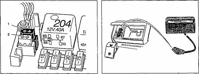
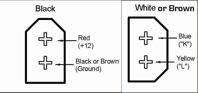
1 Power supply, 2 Removing information
6 Count the number of flashes in the series and write down the code. To decipher its value refer to the table at the end of the chapter.
7 Each code will repeat until you insert the fuse again. Insert and after 6 seconds remove the fuse. After that, the following code will flash.
8 Continue to retrieve the codes until the code 0000 appears, which means that there are no more codes in the BEU's memory.
9 If the code 4444 immediately appears, it means that no DTCs have been registered.
10 At the end of the reading procedure, turn off the ignition.
Bosch Mono-Jetronic (after July 1988), KE-Jetronic, KE-Motranic 1.1 and 1.2, Motronic 2.3 and 2.4
11 Connect the auxiliary switch to the jacks as shown in fig. 6.5 - 6.7 depending on their number. If the car is not equipped with a fault warning light on the dashboard, then also connect the LED.
12 Start and warm up the engine to operating temperature. Note: Oxygen sensor malfunction codes may appear only after a road test that lasts at least 10 minutes.
13 Stop the engine and turn on the ignition.
14 If the engine does not start, turn it with a starter for at least 6 seconds and leave the ignition on.
15 Close the auxiliary switch for at least 5 seconds. Open the switch and the LED or signal light will transmit fault codes, which should be understood as follows.
a) Four digits are indicated by four series of flashes.
b] The first series of flashes means the first digit, the second series - the second digit, etc. down to the fourth.
c) Each series consists of several flashes with a duration of 1 or 2 seconds with short intervals between them. Figures from 1 to 9 are indicated by 1 second flashes, and zero - by a two-second flash.
d] One series from the other is separated by a pause of 2.5 seconds.
e] Code 1231 is reproduced as follows: one 1-second flash, a short pause, two 1-second flashes, a short pause, three 1-second flashes, a short pause, one 1-second flash. An exposure time of 2.5 seconds will repeat the code. Normally black connector
16 Count the number of flashes in series and write down the code. To decipher its meaning, refer to the table at the end of the chapter.
17 Each code will repeat until you again close the auxiliary switch for at least 5.0 seconds, and then open it. After that, the following code will flash.
18 Continue to retrieve the codes until the code 0000 appears, which means that there are no more codes in the BEU's memory.
19 If the code 4444 immediately appears, it means that no DTCs have been registered.
20 At the end of the reading procedure, turn off the ignition and disconnect the LED and the switch.
Bosch Mono-Motronic (35-pin version of the BEU connector 1.2.1 and 45-pin version 1.2.2)
21 Connect the auxiliary switch to the diagnostic connectors as shown in fig. 6.8. If the car is not equipped with a malfunction warning light on the dashboard, also connect the LED between (+) power and pin 33 of the BEU connector (for 35-pin connector] or pin 3 (for 45-pin connector). Note: You will need to disconnect the rear section BEU connector to get to the desired pin without disconnecting the connector.
22 Start and warm up the engine to operating temperature. Note: Oxygen sensor malfunction codes may appear only after a road test that lasts at least 10 minutes.
23 Stop the engine and turn on the ignition.
24 If the engine does not start, turn it with a starter for at least B seconds and leave the ignition on.
25 Close the auxiliary switch for at least 5 seconds. Open the switch and the LED or signal light will transmit fault codes, which should be understood as follows.
a] Four digits are indicated by four series of flashes.
b] The first series of flashes means the first digit, the second series - the second digit, etc. down to the fourth.
c] Each series consists of several flashes with a duration of 1 or 2 seconds with short intervals between them. Numbers from 1 to 9 are indicated by 1 second flashes, and zero - two-second H-1.
d] One series from the other is separated by a pause of 2.5 seconds.
e] Code 1231 is reproduced as follows: one 1 second flash, a short pause, two 1 second flashes, a short pause, three 1 second flashes, a short pause, one 1 second flash. After a shutter speed of 2.5 seconds, the code will repeat.
26 Count the number of flashes in the series and write down the code. To decipher its value refer to the table at the end of the chapter.
27 Each code will repeat until you again close the auxiliary switch for at least 5.0 seconds, and then unlock it. After that, the following code will flash.
28 Continue to retrieve the codes until the code 0000 appears, which means that there are no more codes in the BEU's memory.
29 If the code 4444 immediately appears, it means that no DTCs have been registered.
30 At the end of the reading procedure, turn off the ignition and disconnect the LED and the switch.
Systems with a 16-pin on-board diagnostics connector or 64-pin BEU connector
31 “Flashing" codes are not provided. You must use a code reader.
Removing codes from memory without the help of a reader
Bosch Mono-Jetronic, Mono- Motronic. KE-Jetronic and KE- Motronic
1 To extract codes, use the procedure described in paragraph 3.
2 Turn off the ignition.
3 Short circuit the fuse test contacts over the fuel pump relay (only Mono-Jetronic until July 1988] or close the auxiliary switch [other systems).
4 Turn on the ignition.
5 After 5 seconds, open the switch or remove the fuse. All codes in memory will be erased.
6 Turn off the ignition.
About codes 2341 and 2342 (oxygen sensor)
7 Turn off the ignition and remove the key. Disconnect the BEU connector for at least 30 seconds. Read caution number 3 in the Appendix at the end of the book.
All systems [alternative method]
8 Turn off the ignition and disconnect the wire from the negative terminal of the battery for about 5 minutes.
9 Reconnect the wire to the battery.
Note: The first disadvantage of this method is that the BEU will reset all adapted parameter values to the initial state. In order to re-adjust the system to your engine, you will need to start the engine from a cold state, and then ride the car at different engine revolutions for 20 ... 30 minutes. In addition, it is necessary to allow the engine to idle for about a minute. The second drawback is that you will have to reinstall the protective code of the radio, the current time value and other stored values, which will also be reset when the battery is disconnected. Most useful for removing codes to use the reader.