
Toyota Camry Error Codes

Camry error codes help with the help of computer diagnostics to make the correct "diagnosis", to understand which element, engine sensor, gearbox, etc., has failed. This greatly speeds up car repairs. Modern scanners independently decode error codes, but if you use diagnostic equipment that does not do this, then we will try to help.
Correct diagnostic work Camry 50
The sequence of reading the error code is approximately the same for all Toyota cars:
- with the ignition off, connect the scanner to the diagnostic connector,
- establish a connection between the scanner and the phone via Bluetooth, if the diagnostic program is installed as an application on the smartphone; connect the scanner to the computer of the laptop on which the diagnostic program is installed,
- In the program menu for reading the error code, select the Toyota Camry of the required year and body,
- turn on the ignition or start the engine and start the scan,
- the program will generate error codes that have been saved in the vehicle control units since the last time the fault codes were deleted,
- remove all errors, drive a car 2-3 kilometers and re-read, now the equipment will show only operational problems, and not all, including the fixed ones,
- write error codes, if the program decrypts, then write or save the problems shown,
- at the end of diagnostic operations, turn off the scanner and ignition.
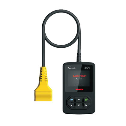
Modern scanners
Now many scanners are presented for reading car error codes that fully decode the error codes. These programs are translated into Russian, easy to use and allow you to customize the parameters of the car. For example, the time when the lights go out, after the ignition is turned off, after how many seconds the interior lights go out during landing, landing, and more.
The owner of the car should think about the purchase of diagnostic equipment. Not bad manufacturers of diagnostic devices: Launch, ELM, Autel, Autocom, Carman.
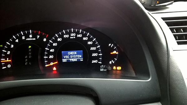
Error codes Toyota Camry 40
Check VSC System - the message appears on the on-board computer screen.
The notification itself Check VSC System does not carry specific information, it is a warning that something is wrong with the car. Significant problems may not be, for example, refuel with a running engine, or recharge a dead battery, a Check VSC System will appear. If there is no breakage, the message will go away, turn off and start the car 10 times, or disconnect the battery terminal for 5 minutes. The notification does not go away, then conduct a computer diagnostics Camry.
P0351, P0352, P0353, P0354, P0355, P0356
Ignition coil errors, the last two can appear only on Toyota V6 engines, for example, 2GR-FE.
The reasons for the appearance of these codes:
- failed ignition coil,
- faulty wiring to coils
- broken electronic control unit.
To accurately diagnose the fault, measure the electrical signal from the ignition coil with an error with an oscilloscope. If there is no oscilloscope, you can swap a potentially faulty coil with another. For example, there is an error P0351, moved the coil from the first cylinder to the second, now the scanner shows P0352 - the problem is in the coil, if the code remains the same P0351 - the wiring or the ECU is faulty.
P0172
Error P0172 - too rich air / fuel mixture. Causes:
- air intake system
- faulty jets,
- mass air flow sensor not working correctly,
- fuel pressure out of limits,
- exhaust gas leak
- the problem is in the circuit or in the oxygen sensor itself,
- ECU.
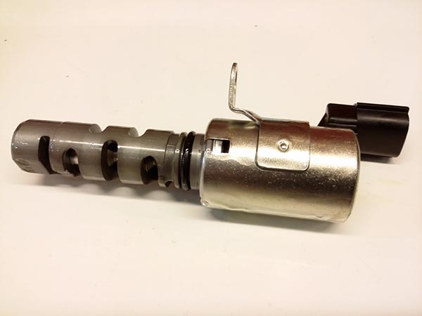
For an accurate "diagnosis", refer to an experienced master.
One of the ways to eliminate the error is to replace the valve VVT-I.
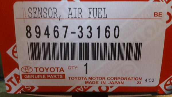
P2237
P2237 - open circuit of the oxygen sensor (A / F) pump current circuit, P2238 - weak current in the oxygen sensor (A / F) pump current circuit (1 row 1). It's about the lambda probe, installed before the catalyst, which is located next to the engine. This error may not affect the behavior of the car, but fuel consumption will increase. We want to warn against replacing this sensor with a non-original one.

The use of this head will not remove the heat shield when replacing broken lambda probes.
P0137, P0157
P0137, P0157 - low voltage in the oxygen sensor circuit (row 1, row 2 sensor 2).
Causes of P0137, P0157 errors:
- open circuit, breaking of the heated oxygen sensor circuit, row 1.2 sensor 2,
- faulty lambda probe (heated oxygen sensor),
- sensor air-fuel mixture row 1.2 sensor 1,
- exhaust gas leakage.

If the active ratio is enriched during active air-fuel ratio control, but the output voltage of the heated oxygen sensor is less than 0.21 V (lean), the ECM regards this as an excessively low sensor output voltage and detects DTC P0137 or P0157. If during the active air-fuel ratio control the specified ratio is depleted, but the output voltage is more than 0.59 V (enrichment), the ECM regards this as an excessively high output voltage of the sensor and registers DTC P0138 or P0158.
If replacement of the sensor did not bring results, then the master could change the wrong sensor (this happens often), or the problem is not in the sensor, but in the circuit or in the exhaust leak.
Check all the connectors, they could oxidize, moisture could get into them. Visually inspect the wiring for integrity. If the visual circuit is in order, then check its operation using an oscilloscope.
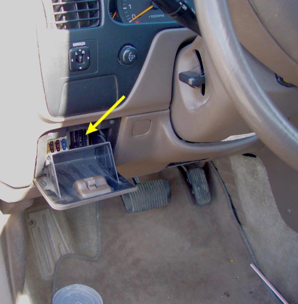
Camry Diagnostic Connectors 40
Diagnostic connector in the Camry 30 is to the left of the steering column.
OBD 2 diagnostic connector Camry 40, 50 and 55 is located under the steering column below the dashboard next to the pedal assembly (photo attached).
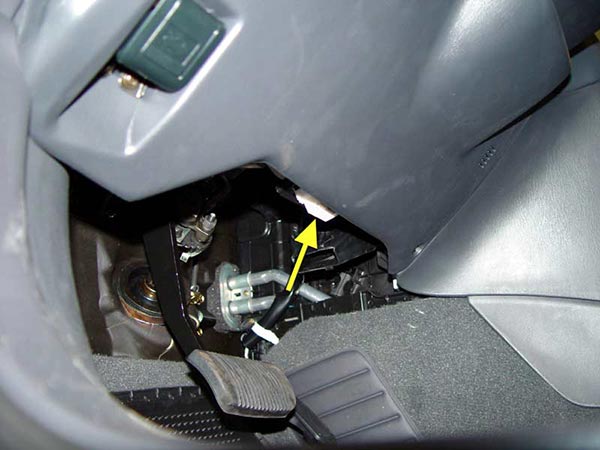
The location of the diagnostic connector Camry
Error codes and their interpretation for Toyota Camry cars from 2006 release
|
P0010 |
Camshaft Position Sensor A Circuit (Row 1) |
1. Open or short in valve circuit oil supply to oil cooler ( OCV ) 2. OCV 3. Electronic engine control unit (Electronic control unit) |
|
P0010 |
Position of a camshaft And - gazoras overrun or system performance (Row 1) |
1. Gas distribution phases 2. OCV 3. OCV filter 4. Cog wheel 5. Electronic control unit |
|
P 0012 |
Camshaft position a - gazoras delays with excessive delay (row 1) |
The same as for P 0011 |
|
P0016 |
The relationship between the positions of the crankshaft and camshaft (sensor A, row 1) |
1. Mechanical system (leaping or growing timing chain) 2. Electronic block of management |
|
P0031 |
Weak current in the control circuit of the oxygen sensor heater ( A / F) (row 1 sensor 1) |
1. Open in the air-to-fuel ratio ( A / F ) sensor heater circuit 2. Heater sensor A / F (sensor 1) 3. Engine compartment distribution unit (electronic fuel injection system ( EFI ) relay ) 4. Electronic block of management |
|
P0032 |
Strong current in the control circuit of the oxygen sensor heater ( A / F ) (row 1 sensor 1) |
1. A / E Sensor Heater Circuit Short 2. A / E Sensor Heater (Sensor 1) 3. Engine compartment distribution unit ( EFIrelay ) 4. Electronic block of management |
|
P0037 |
Weak current in the control circuit of the oxygen sensor heater (sensor 1 row 2) |
1. Break in oxygen sensor heater target ( HO 2) 2. Heater HO sensor 2 (sensor 2) 3. Engine compartment distribution unit ( EFI relay ) 4. Electronic block of management |
|
P0038 |
Strong current in the control circuit of the oxygen sensor heater (sensor 2 row one) |
1. Short circuit in the oxygen sensor heater circuit (HO 2) 2. Heater HO sensor 2 (sensor 2) 3. Engine compartment distribution unit ( EFI relay ) 4. Electronic block of management |
|
Code |
Malfunction |
Faulty plot |
|
P0100 |
Circuit sensor mass or volume air flow |
1. Open or short in the air flow sensor ( MAF )circuit 2. Sensor mass expense of air 3. Electronic block of management |
|
P0102 |
Low level signal at the input circuit of the sensor mass or volume air flow |
1. Open or short in air flow sensor circuit 2. Sensor mass expense of air 3. Electronic block of management |
|
P0103 |
High level signal at the input circuit of the sensor mass or volume air flow |
1. Open or short in air flow sensor circuit 2. Sensor mass expense of air 3. Electronic block of management |
|
P0110 |
Malfunction in the intake air temperature sensor circuit |
1. Open or short in the intake air temperature sensor circuit ( IAT ) 2. Sensor I AT (built into the mass air flow sensor ( MAF ) 3. Electronic block of management |
|
P0112 |
Low level signal on the inlet air intake sensor circuit |
1. Short circuit in the IAT sensor circuit 2. IAT sensor (built-in 8 mass air flow sensor) 3. Electronic block of management |
|
P0113 |
High level of the input signal of the inlet air temperature sensor circuit |
1. Open circuit IAT sensor 2. IAT sensor (built into mass air flow sensor) 3. Electronic block of management |
|
P0115 |
Malfunction in the coolant temperature sensor circuit fluid |
1. Open or short in the coolant temperature sensor (ECT) target 2. ECT Sensor 3. Electronic block of management |
|
P0116 |
Malfunction in the coolant temperature sensor circuit liquid, due to the output of its characteristics beyond the permissible range / true value of the parameter |
1. Thermostat 2. ECT Sensor |
|
P0117 |
Low level signal on the input of the sensor target coolant temperature |
1. Short circuit in the ECT sensor circuit 2. ECT sensor 3. Electronic block of management |
|
P0118 |
High level signal at the sensor circuit input by that coolant temperature |
1. Open circuit ECT sensor 2. ECT Sensor 3. Electronic block of management |
|
P0120 |
Sensor / Switch Circuit Malfunction -A- Polo throttle / pedal |
1. Throttle Position Sensor ( TP ) (built into the throttle body) 2. Electronic block of management |
|
P0121 |
Throttle / Pedal Position Sensor / Switch A Circuit Malfunction Related to Range / Characteristics |
TP sensor (built into body / throttle) |
|
P0122 |
Low level signal at the input of the sensor circuit polo throttle pedal A |
1. TP sensor (built into the throttle body) short circuit in the VTA 1 circuit 2. Broken in VC circuit 3. Electronic block of management |
|
P0123 |
The high level of the signal at the input of the sensor circuit Pedal / Throttle A Positions |
1. TP sensor (built into the throttle body) 2. Breakage in a chain VTA1 3. Breakage in a chain E2 4. Short circuit between VC and VTA 1 targets 5. Electronic block of management |
|
P0136 |
Malfunction in the oxygen sensor circuit (sensor 2 rows 1) |
1. Open or short in HO 2 sensor circuit ;(sensor 2) 2. HO 2 sensor ; ( sensor 2) 3. Heater HO 2 sensor ; ( sensor 2) 4. Air-to-fuel ( A / F ) ratio sensor (sensor 1) 5. Engine compartment distribution unit ( EFIrelay ) 6. Gas leakage from exhaust system |
|
P0137 |
Low voltage in the oxygen sensor circuit (Row 1, Sensor 2) |
1. HO 2 sensor circuit open (sensor 2) 2. Sensor BUT; ( sensor 2) 3. Heater BUT sensor ; ( sensor 2) 4. Engine compartment distribution unit ( EFIrelay ) 5. Exhaust gas exhaust system |
|
P0138 |
Oxygen Sensor Circuit High Voltage (Sensor 2, Row 1) |
1. Short circuit in the HO 2 sensor circuit(Sensor 2) 2. HO 2 sensor (sensor 2) 3. Internal circuit malfunction Electronic control unit |
|
P0171 |
Excessive impoverishment of the mixture in the system (row 1) |
1. System fence of air 2. Nozzle littered 3. Sensor mass expense of air 4. ECT Sensor 5. The pressure in the fuel system 6. Exhaust gas leaks from exhaust system 7. Open or short in A / F sensor circuit (Sensor 1) 8. Sensor A / F (sensor 1) 9. A / F sensor heater (yes chic 1) 10. Engine compartment distribution unit ( EFIrelay ) 11. A / F Sensor Heater Circuit and EFI Relay 12. Connections hose ventilation crankcase 13. Hose and papin crankcase ventilation 14. Electronic block of management |
|
P0172 |
Excessive enrichment of the mixture in the system (row 1) |
1. A leak through nozzle or blockage 2. Sensor mass expense of air 3. ECT Sensor 4. System ignition 5. The pressure in the fuel system 6. Gas leakage from exhaust system. 7. Breakage or a short closure at chains sensor A / F (sensor 1) 8. Sensor A / F (sensor 1) 9. Heater sensor A / F (sensor 1) 10. Engine compartment distribution unit ( EFI relay) 11. A / F sensor heater and EFI relay targets 12. Electronic block of management |
|
P0220 |
Pedal / Throttle Position Sensor Circuit |
1. TP sensor (built into the throttle body) |
|
P0222 |
Low level at the input of the pedal / throttle position sensor circuit "B" |
1. TP sensor (built into the throttle body) 2. A short short circuit in the VTA2 circuit 3. Broken in VC circuit 4. Electronic block of management |
|
P0223 |
Pedal / Throttle Position Sensor B Circuit High Input |
1. TP sensor built into throttle body 2. Breakage in a chain VIA2 3. Breakage in a chain E2 4. Short circuit between VC and VIA 2 circuits |
|
P0300 |
Irregular / Multiple Ignition Detection in Cylinder |
1. Open or short in engine wiring harness 2. Connection connector 3. Connections vacuum hose 3. System ignition 5. Injector 6. The pressure in the fuel system 7. Sensor mass expense of air 8. ECT Sensor 9. Pressure compression 10. The gap in the drive valves 11. Phases gas distribution 12. Hose and valve ventilation crankcase 13. Compound hose ventilation crankcase 14. System fence of air
|
|
P0301 |
Ignition registration registration in cylinder 1 |
Same as for P 0300 |
|
P0302 |
Misfire detection in cylinder 2 |
Same as for P 0300 |
|
P0303 |
Exposure of residence permit in cylinder 3 |
Same as for P 0300 |
|
P0304 |
Misfire detection in cylinder 4 |
Same as for P 0300 |
|
P0327 |
Low level signal at the input of the knock sensor circuit 1 (row 1 or a separate sensor) |
1. short closure at goals sensor detonation and 2. Sensor detonation 3. Electronic block of management |
|
P0328 |
high signal level at the input of the knock sensor circuit 1 (row 1 or a separate sensor) |
1. breakage at goals sensor detonation and 2. Sensor detonation 3. Electronic block of management |
|
P0335 |
Crankshaft Position Sensor A Circuit |
1. Open or short in crankshaft position sensor (CKP) circuit 2. Sensor TFR 3. Plate sensor TFR 4. Electronic block of management |
|
P0339 |
Intermittent Crankshaft Position Sensor A Signal |
Same as for P 0335 |
|
P0340 |
Camshaft Position Sensor Circuit "A * (Row 1 or Separate Sensor) |
1. Open or short in the distribution position sensor (CMP) circuit 2. CMP sensor 3. Distributive shaft 4. Jump chain the drive gas distribution bodymechanism 5. Electronic block of management |
|
P0351 |
Ignition coil low / high voltage circuit A |
1. System ignition 2. Open or short in IGF 1 and IGT between the ignition coils (1-4) and the Electronic control unit 3. Coils Ignition No. 1 - 4 4. Electronic block of management |
|
P0352 |
Ignition coil low / high voltage circuit V |
Same as for P 0351 |
|
P0353 |
Ignition coil low / high voltage circuit C |
Same as for P 0351 |
|
P0354 |
Ignition coil low / high voltage circuit Niya D |
Same as for P 0351 |
|
P0420 |
Efficiency of the catalytic neutralization system below the threshold level (row 1) |
1. Reception room pipe (with TWC) 2. Exhaust gas leaks from exhaust system 3. Air-to-fuel ( A / F ) ratio sensor (sensor I ) 4. Heated Oxygen Sensor (H O 2) (Date 2) |
|
P0443 |
Circuit control valve purge system caught fuel vapor |
1. open or short in purge vacuum valve circuit 2. Electrovacuum valve purge 3. Electronic block of management |
|
P0500 |
Vehicle Speed Sensor Malfunction |
1. Open or short in speed signal circuit 2. Shield appliances 3. Electronic block of management systemsanti-skid 4. Sensor speeds the car 5. Electronic block of management |
|
P0504 |
A / V Brake Switch Signal Correlation |
1. Short circuit in the signal circuit of the brake light switch 2. Switch table signals 3. Fuse STOP 4. IGN fuse 5. Electronic block of management |
|
P0505 |
Malfunction of the idle speed control system |
1. ECTS (electronic throttle control system Noah valve) 2. System fence of air 3. Compound hose ventilation crankcase 4. Electronic block of management |
|
P0560 |
Invalid system voltage |
1. Open circuit in the auxiliary power supply 2. Rechargeable battery 3. findings rechargeable batteries 4. Fuse FFI №1 5. Electronic block of management |
|
P0604 |
Internal error operatively memory (RAM) control unit |
Electronic block of management |
|
P0606 |
Processor Electronic Control Unit / PCM |
Electronic block of management |
|
P0607 |
Workers specifications block of management |
Electronic block of management |
|
P0617 |
High level signal in the starter relay circuit |
1. Parking / Neutral Position Sensor ( PNP ) (for models with automatic transmission) 2. Clutch release switch (for models with manual transmission) 3. Chain relay starter 4. Ignition lock b. Electronic control unit |
|
P0657 |
Actuator power supply circuit / open circuit |
Electronic block of management |
|
P0724 |
High level signal in the circuit of the brake switch B |
1. Short circuit in the signal circuit of the brake light switch 2. Switch brake lights 3. Electronic block of management |
|
P2102 |
Weak current in the motor circuit of the throttle actuator |
1. Open circuit in the throttle actuator circuit 2. Drive unit throttle dampers 3. Electronic block of management |
|
P2103 |
Strong current in the motor circuit of the throttle actuator |
1. Short circuit in the throttle actuator circuit 2. Drive unit throttle dampers 3. Throttle damper 4. Housing throttle valve assembly 5. Electronic block of management |
|
P2 111 |
Throttle Control System - Jadeopen position |
1. Drive unit throttle dampers 2. Housing throttle valve assembly 3. Throttle damper |
|
P2112 |
Throttle Control System - Jadeclosed position |
Same as for P 2111 |
|
P2118 |
Throttle actuator motor current out of range / invalid mode |
1. Open circuit FTCS power supply 2. Rechargeable battery 3. findings rechargeable batteries 4. ETCS fuse 5. Electronic block of management |